DENNIS HANCOCK
Dennis@DennisHancock.com
Me
My Profile
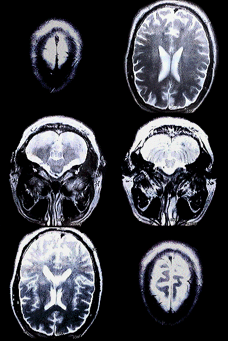
My Brain
 |
I Develop Custom 3D Modeling And Simulations For Challenging Science and Engineering Problems.
This places me at the always exciting intersection of hardware and software.
I Also Work As An Electro-Optics Applied Physicist.
I live on the San Francisco Peninsula.
My world famous Photographic Lens Performance blog. Be the first to read it!
Photo restoration is a fun avocation that brings together many skills from my professional background.
A few photo awards. 'Cause a little recognition is nice sometimes.
 |
My Resume
3D Technical Modeling Examples I've Authored
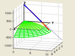
3D Ray Tracing The Atmosphere
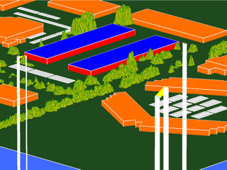
3D Ray Tracing A City
3D Ray Tracing A Walking Man
3D Ray Tracing From Space
 |
 |
 |
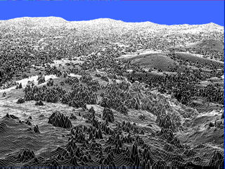 |
SAR Lab Experiment
Haptics
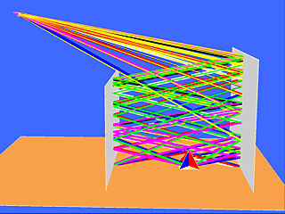 |
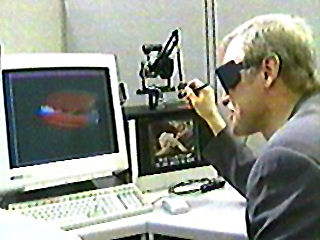
|
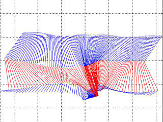
Raytraced Echo Paths For A Bi-static Radar,
A Corner Cube, And Three Reflecting Surfaces
Still.
Click For The Details
Some Optics Efforts I've Modeled With My Own Softwares
(Literally From X-Rays To Radio Waves)
And/Or Performed
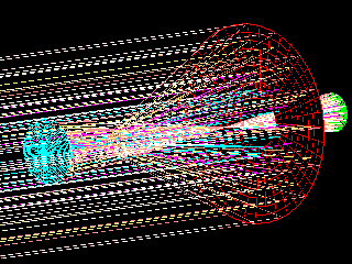
Fixing The Hubble Telescope With Virtual Reality
Procedural Ray Tracing
Geometric Distortion
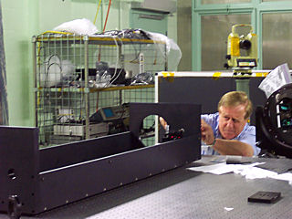
A Metrology Effort
Adaptive Optics
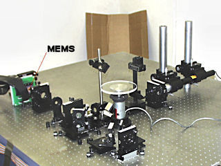
A Hardware Instrumentation Effort
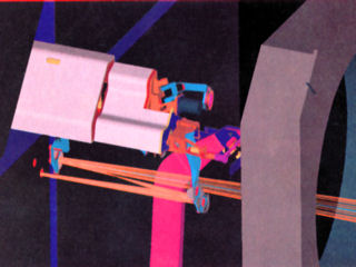 |
 |
 |
 |
Ultra High Precision Optical Geometric Distortion Measurement
 |
For Measurement Of Geometric Distortion To 10nm Levels, It's Mandatory To Know The Exact Shape of Your System's Point Spread Function Across The Entire Field.
Here, I Show My Computations Of The Axial PSFs For A Single Field Position
For The Ideal Case Of Aberration Free Imaging And Three Realizations Of System Apodization.
"If you don't model it, you're likely not to measure it."
Partially Coherent Imaging With DeFocus Aberration
A Calculation Perfect For A GPU!
 |
Some Imaging Applications Need To Consider Electric Field Coherency And Optical Aberrations To Predict Performance With High Accuracy.
Here, Diffraction Elliptical Spot Images Are Formed On A Tilted Plane Assuming Incoherent, Partially Coherent, And Fully Coherent E-Fields With Varying Amounts Of Defocus Aberration.
A Hypothetical Optic Is Trying To Form The Same Image (Green Oval) In All Frames. A Transparent, Black Box is Drawn For Reference.
Aberrations From An Actual Optical Design Are Easily Accommodated And Alter These Results Accordingly.
Vertical Scaling Is Log10 And All Frames Are Normalized By The Aberration Free Case.
Click Here For Other Advanced Examples
"If you don't model it, you'll likely not understand it."
Extremum Raytrace For A Free Electron Laser (FEL) X-Ray Beamline
At A National Particle Accelerator Lab
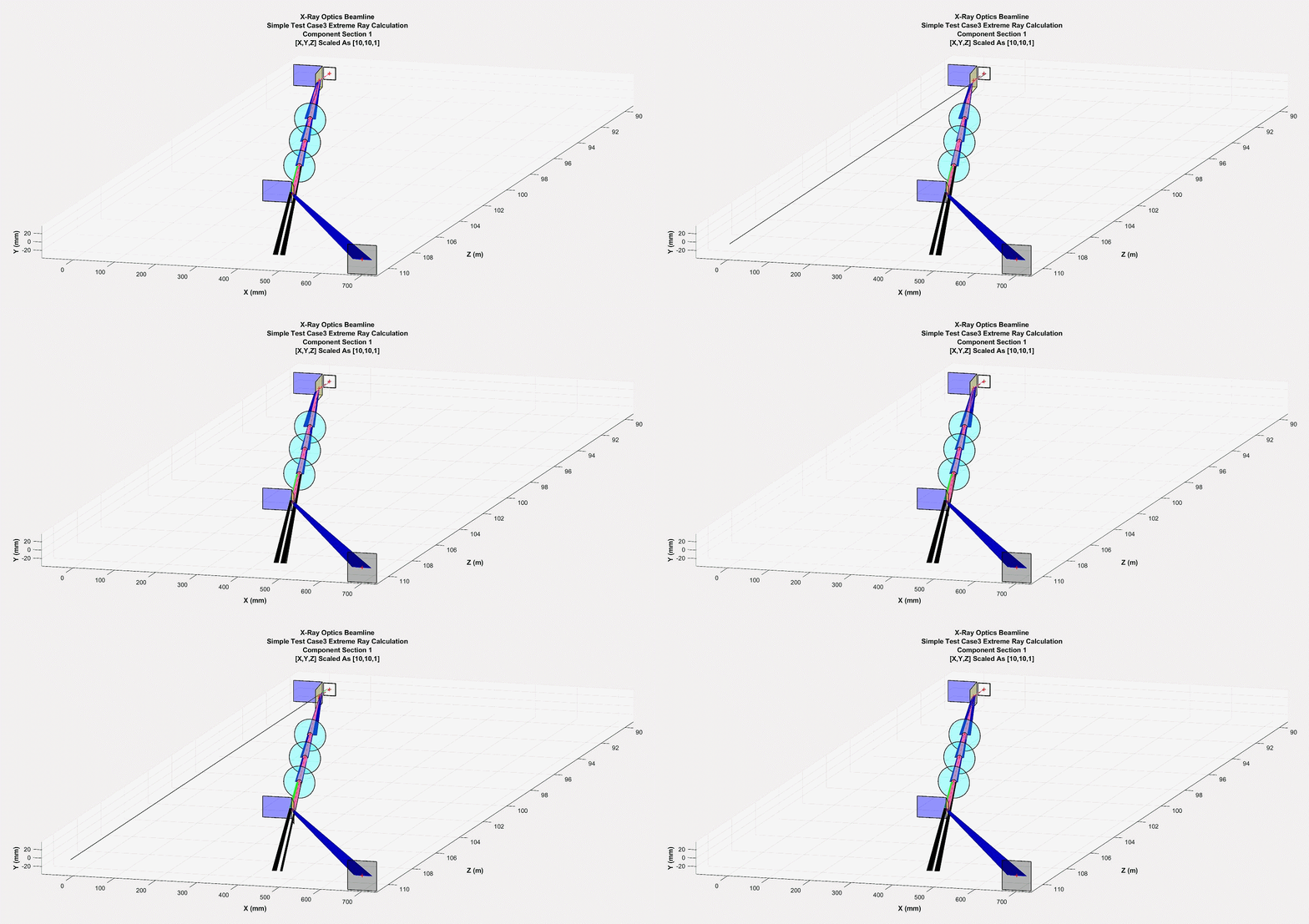 |
The 'Blue', 'Green', and 'Pink' Rays Are Controlled By The X-Ray Optical Elements
The Lethal And Destructive 'Black' Rays Are Not Controlled In This Early Design
A Single, On-Axis Source Ray Scanning +/- 6mm Is Modeled Here
"You do not want to operate this high power x-ray laser beamline until you model it."
Satellite Altimeter Radar Echo Return Over An Ocean/Land Interface
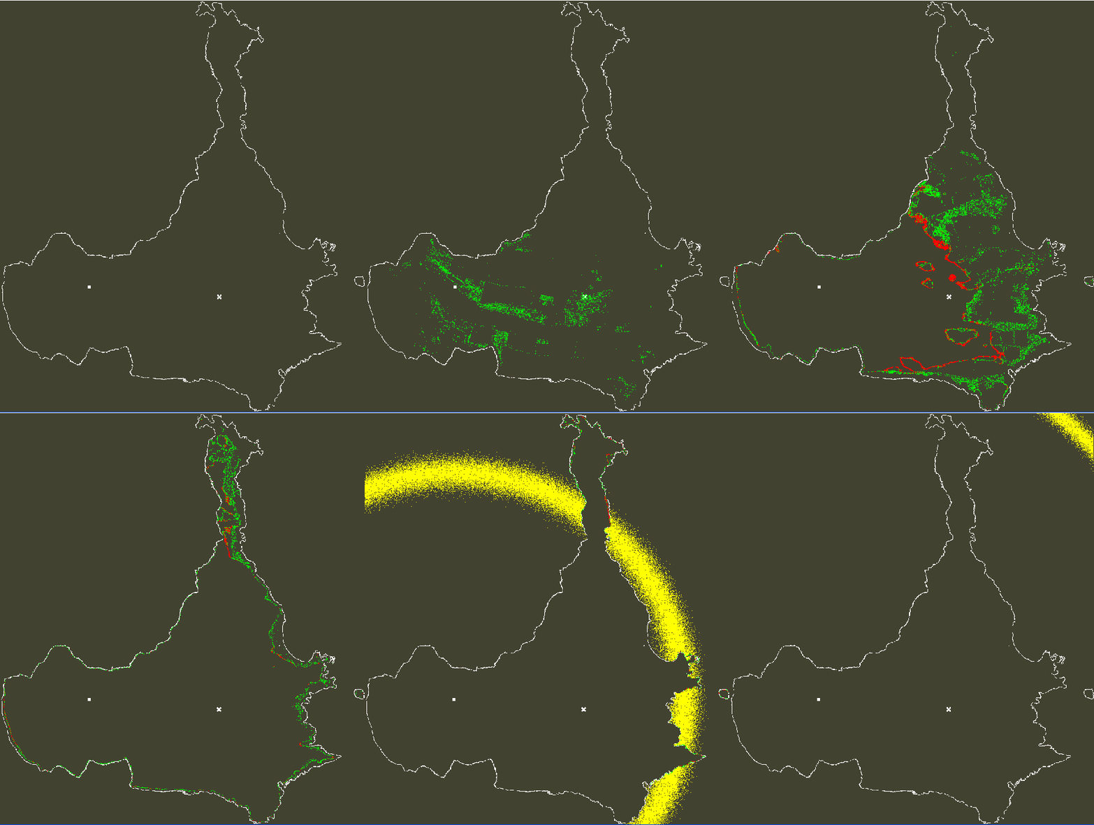 |
This simulation shows the return echo from a satellite radar situated over a 3D lidar-acquired island model (42.583368N, 10.079077E.)
The altimeter is placed 695Km above the white square (lower left,) ensuring first returns come from land.
This island has a maximum height of 29 m and an average height of 10m above the sea.
Each frame is spaced by 3.125 nano-seconds.
Color coded returns: Vegetation-->Green; Land and Buildings-->Red; Rough, Gaussian Ocean-->Yellow.
Author:Dennis M Hancock
Last Updated: 5Nov18
Cogito. Ergo Scio.